Select and Move
Selecting through the Alpha channel
When stacking layers, Autograph builds a Selection Map based on both the Position of each element in the layer stack from bottom to top, and each layer’s Alpha channel. This lets you select elements you actually see in the Viewer, without worrying about layer bounding boxes and transparent pixels that might prevent you from selecting a visible element.
Clicking within the Viewer goes through each layer's Alpha channel to eventually reach a pixel with an opacity higher than 0.5 (50% transparent) and selects the corresponding layer. This selection takes transparency into account after applying Modifiers such as a Color Difference Key, used to remove a green screen.
In the video below, clicking on the green screen moves the entire layer. But once the Color Difference Key is activated, you can click through the transparent pixels to select and move the image used as background.
Note
The flashes that appear when the mouse is moved are the result of the Selection Hint, which allows you to preview which layer will be selected. When hovering over a layer, it lights up in the Timeline at the same time so you can see its position in the Stack.
Blending modes and selection map
The Alpha channel is not the only factor used when creating a selection map. The layer blending mode used also defines areas through which you can click.
In the following example, a dust image without an Alpha channel is added to the top of the Stack in Screen mode. The dark parts let you see the rest of the Stack while the brighter parts hide it.
Screen mode considered the black parts as transparent and Autograph takes this into account when creating the selection map. So it’s possible to click through these disappearing black parts to select lower layers in the Stack. This selection is accurate to the pixel.
Selecting based on bounding boxes
For layers containing very thin elements such as text, the transparency-based selection may not be the best option. Autograph also provides a selection mode based on layer bounding boxes instead, which is available in th Viewer options at the top-left.
The Selection Method option contains two modes:
- Select with Alpha channel (default)
- Select with bounding box
In this second mode, used for selection in After Effects, the selection map is made from the full bounding boxes, without checking transparency.
In order to select layers more easily, especially the ones hidden behind other layers, you can also rely on the Visual stack.
Transform Parameters
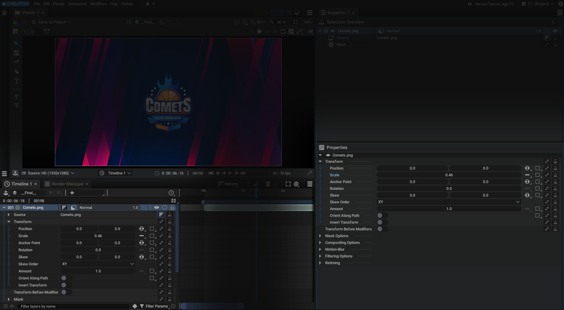
After linking a graphic element to a layer’s Source parameter, you can use the Transform section to define layer Position, Rotation, Scale and Skew.
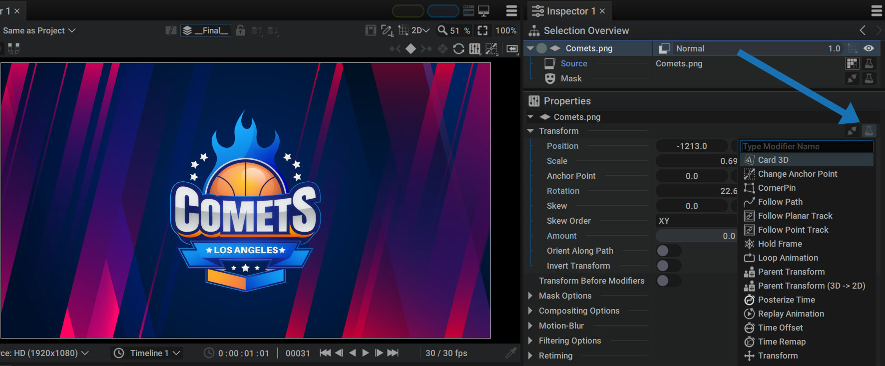
You can access this section either by unfolding a layer in the Stack or by selecting it and clicking on the first line in the Selection Overview.
In this Transform sub-section, you will find the following parameters that use Autograph's specific coordinate system:
- Position: 2D param, in unified mode by default
- Scale: 2D param, in single mode by default
- Anchor Point: 2D param, in unified mode by default
- Rotation: 1D param, in single mode only
- Skew: 2D param, in unified mode by default
- Skew order: non-numerical param; defines whether the X Skew will be applied before or after the Y Skew
- Amount: weight of the global transformation. Can also take values outside the 0-1 range, even negative values
- Inverse Transform: allows you to invert the transformation matrix
Autograph offers different ways of controlling these parameters:
- By manipulating them with the mouse
- By manually entering a value
- By using arrows with the Alt key to move a layer by 1 or 10 pixels in the Viewer
- By entering mathematical operations
- By using Javascript expressions
These different methods are described in detail in the changing a parameter value section of the Parameter Management chapter.
Anchor Point
The Anchor Point is the reference point used when determining a layer's Position values.
Since an image is made up of a large number of pixels, saying that it is currently at Position (160,80) for example, does not clearly indicate what it is in relation to - is it its upper-right corner, lower-left corner, or its center that is at these coordinates?
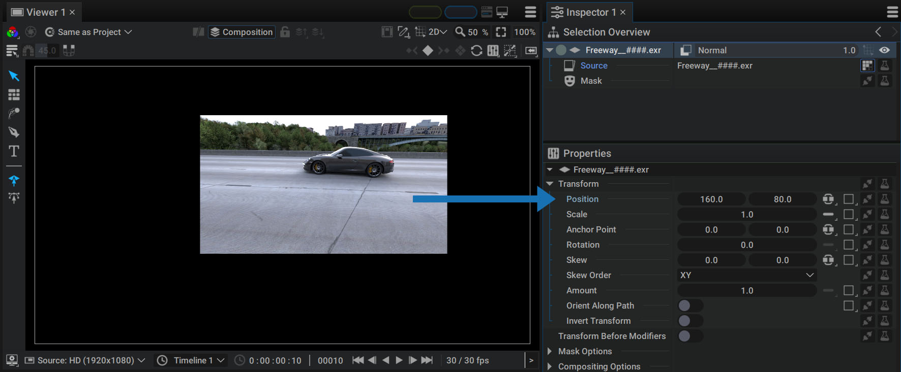
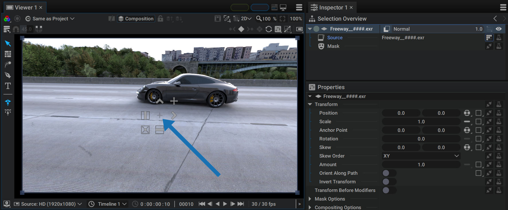
The values displayed in Position are therefore those of the Anchor Point positioned at the center of the layer Source and with values (0,0) by default. In order to view the position of the Anchor Point, simply position the cursor over the Viewer with the 2D Transform Tool activated.
It is represented by a small "+" sign in the middle of the Transformation Widget:
Warning
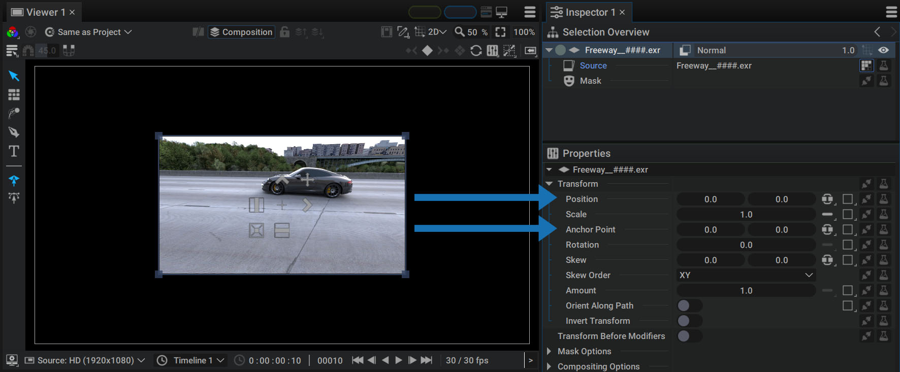
Unlike After Effects, Autograph's coordinate system places the (0,0) coordinate at the center of the composition. But for a layer with Position (0,0) to be perfectly centered, the Anchor Point must also be centered on its Source when its value is (0,0). Therefore, whatever the size of the Source used by a layer, the Position and Anchor Point of (0,0) will always place it at the center of the composition.
Let's use the example of a 960×540 pixel image. By dragging it into a FullHD(1920x1080) composition, it will be placed in the center of the composition, with an Anchor Point in the center of the layer source.
Changing the Anchor Point values will not change the position of this reference point; but, it will cause all image pixels to shift accordingly. If your image is 960 pixels wide, that means it extends 480 pixels to the left and 480 pixels to the right in relation to its center.
In the video below, by entering the value 480 in the X component of the Anchor Point parameter, we place it on the right edge of the image; but, since the Position values will remain the same, all Source pixels will move to the left, until reaching the right edge.
This Anchor Point is also used as a pivot point during a rotation or as a suction or expansion point during a scale change.
If you move this layer, the Position values will be modified, but those of the Anchor Point won't as they will remain positioned at the right edge of the Source.
Moving the Anchor Point
We've just seen that changing the Anchor Point values shifts all the pixels, leaving this reference point in place. If you want to move this Anchor Point without moving the Source image of a Layer, you also need to change the Position values while compensating for the Scale variations.
Fortunately, this can be done automatically by pressing the Ctrl/Cmd key and clicking on the "+".
Redefining the Anchor Point
In the top right-hand corner of the Viewer, there is a toolbox dedicated to resetting the Anchor Point according to various rules. That allows you to easily move the Anchor Point to a corner, edge, or the center of the image, without moving the image pixels.
New values will be calculated for both the Position and the Anchor Point:
You can choose to fix the Anchor Point according to:
- Individual Bounding Box: the Anchor Point will be positioned differently for each selected layer
- Selection Bounding Box: the Anchor Point will be computed in relation to the global bounding box of the entire selection
- Composition: the Anchor Point will be calculated according to the composition format
Info
This tool can also be used when several Paths or Path Groups are selected within a Shapes Generator
Transformation Amount
Amount is the last numeric parameter of the Transform section and it allows you to determine the influence of this transformation by acting on it as a multiplier.
By setting this value to 0, the transformation has no effect and the layer returns to its original place when it was added to the stack - in the center of the composition.
Note that you don't have to limit yourself to the 0-1 interval. If a layer in the center of the composition is moved 200 pixels to the right and the Amount is set to 2.0, then it will move twice as much, bringing the layer 400 pixels to the right.
Similarly, setting this value to -2.0 will not only move the layer twice as far, but it will also move it in the other direction, to the left at -400 pixels.
Animate only with Transformation Amount:
If, during an animation, a logo is to end up in the middle of the screen, with a Scale of 1.0 and a Rotation of 0.0, we can move it to the first frame and then animate the Amount parameter using two keyframes, a Generator, or a Modifier(such as the Animator).
In the video below, we apply an Elastic interpolation (one of the 49 available interpolation types) to the first keyframe:
Should the layer not end up in the center of the image, you can then add Transform Modifiers to shift it.
Reversed Order of Transform Modifiers
At the beginning of the defining a parameter chapter, we mention that the Transform section is both a group of parameters and a parameter itself.
This is shown by the existence of Generator and Modifier slots:
Matrix Concatenation and Unique Rasterization:
All transformation parameters that make up the Transform section, including Amount, end up applying what is called a Transformation Matrix on the layer. This is a mathematical object that allows you to store changes in Position, Rotation, Scale, and Skew in a single element.
The difference between Image Modifiers and Transform Modifiers(such as Corner Pin) is that they will act directly on this matrix, and concatenate between them.
Once this resulting matrix is obtained, Autograph applies the corresponding transformation in one go, which allows you to have only one rasterization, thus avoiding the appearance of pixelation effects.
Reversed Order:
A very important point to keep in mind when adding these transformation Modifiers (and ONLY in the case of transforms):
Mathematics dictates that concatenating matrices is always done starting from the last one, going back gradually to the first one. Autograph chooses to represent these Modifiers in the same order and not take any liberties with this mathematical tool and respect this norm.
As a result, there is a major difference with all the other Modifiers in the software.
Warning
The list must be read from bottom to top in order to know the order in which these Transform Modifiers are executed.
Inverse Transform
This option allows you to invert the transformation matrix. It is particularly useful when one transformation is linked to another, allowing for compensation when stabilizing a tracked plate, for example.
3D Transformation
When a layer has its 3D option enabled, the current Transform section is converted to another one with 3D parameters.
To learn more about this, please refer to the Layer - 3D Mode section.
Moving layers with the transformation widget
Once one or more layers are selected, placing the mouse over the Viewer brings up a transformation widget.
By default, it displays:
- A blue frame to resize the layer
- Controllers to change the size and position of the layer
This widget has two modes, allowing two types of transformation to be performed in each:
- Move / Scale: in this first mode (the default one), you can modify the Position and Scale parameters.
- Rotate / Skew: pressing the Alt/Option key replaces these controllers with alternate ones for modifying Rotation and Skew parameters
To rotate a layer:
- Place your cursor outside the widget.
- Hold down the left mouse button and draw a circle in the desired direction.
Pressing the Alt/Option key actually changes one of the transformation options, located at the top-left of the Viewer.
To see this, simply open the options box and press this key:
The video above shows that it is possible to change this default option, which will reverse the behavior of the Alt/Option key.
- Rotate / Skew will be available by default, without pressing this key.
- Move / Scale will be accessible by pressing the Alt/Option key.
Info
A layer can also be selected and moved by clicking and dragging one of its pixels. This widget transformation is not mandatory and can be hidden using the Viewer's overlays options.
Using the Blue Frame and its Options
The blue frame can be used to resize the layer - with or without preserving its aspect ratio.
The top-left box offers two options, which can take two states:
- Uniform Scaling: press the Shift key to change the status without going through the menu
- Uniform: preserves the layer's aspect ratio when the blue frame is manipulated
- Separated: independently modifies horizontal and vertical resizing
- Centered Scaling: press the Ctrl/Cmd key to change the status without going through the menu
- Center: sets the pivot point at the center of the Bounding Box
- Opposite Corner: sets the pivot point on the opposite corner to the one being handled
Local or Global Transformation Widget
After applying a rotation to a layer, the controllers dedicated to Position, Scale, and Skew also orient themselves according to this angle, because the Transform Space option defaults to Local mode.
However, it is possible to switch to Global mode, so that controllers are oriented parallel to the coordinate system's horizontal and vertical axes.
Pixel-by-pixel magnetization
When the Viewer zoom factor is not 100%, the Transform Widget can move a layer between two pixels. In this case, the position values are not integers, which may cause the layer image to be slightly blurred by the pixel filtering.
This option at the top of the Viewer (also known as Pixel Snapping or Pixel Perfect) rounds Position values when moving.
In the video below, pay close attention to the Position values in the Inspector with and without this option enabled:
Warning
To avoid pixel filtering, you'll also need to set the Scale to 1.0 and the Rotation to 0.0. This snapping option is very useful, for example, to ensure that a TV channel logo is always as sharp as possible on screen.
Angle magnetization
The angle defined by the widget in Rotation mode can be constrained to a certain step size. To do this, activate the option at the top-left of the Viewer and set the value in degrees.
This option can be temporarily activated/deactivated during rotation, by pressing the Shift key:
Individual or common anchor point when transforming several layers
When several layers are selected, transformations are computed according to the Anchor Point option status.
- Individual Origins: each layer is transformed relative to its own Anchor Point
- Anchor Point: a common Anchor Point is defined for the selected layers, at the midpoint.
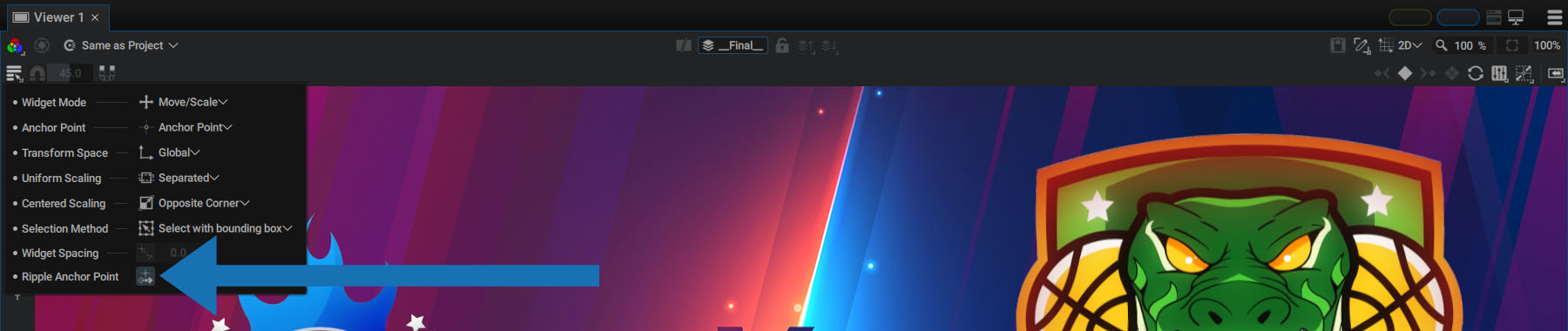
Ripple mode
This option is enabled by default and allows you to move an Anchor Point while keyframes have been added to the Position.
All Position keyframes will be recomputed according to this new Anchor Point:
Warning
This mode only compensates for Position keys. If the Rotation, Scale, and Skew parameters have been animated, the animation will be different.
Widget Spacing
Even though they're transparent, widget controllers can sometimes partially obstruct a layer of the same size.
The Widget Spacing option adds an offset defined in pixels to all controllers, to move them further away from the center of the widget.
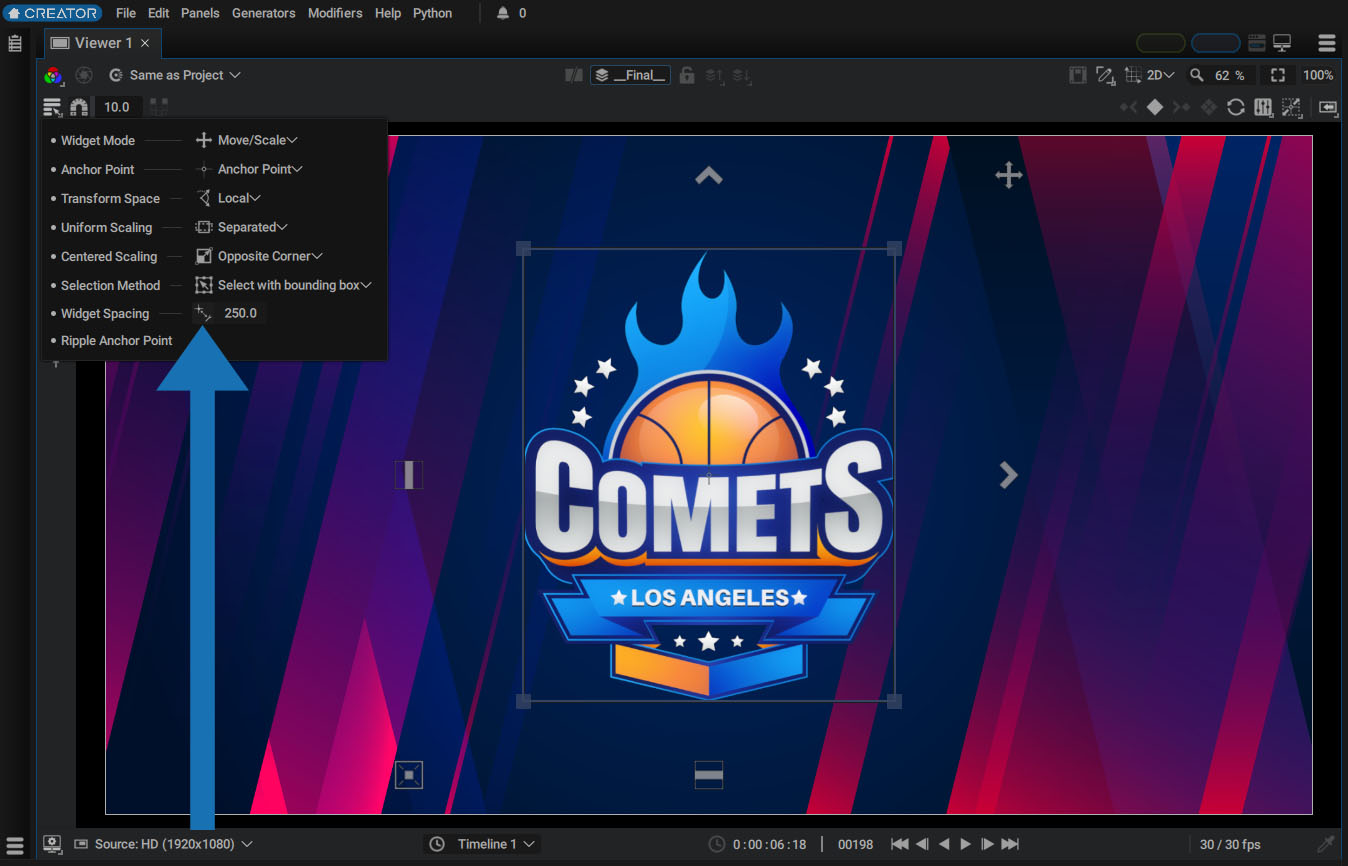
There is a button to the left of this value marked by the blue arrow which allows you to quickly deactivate/reactivate this offset.